Development Host Connections
To communicate with the G3 module during development, you must connect:
The Debug Interface (a.k.a. the Linux System Console)
The Ethernet
In addition, many of our demos support I/O on the RS-232 port so it’s usually a good idea to have that setup as well.
The steps on this page walk you through this process.
Important
The G3 module should not be powered on for all procedures in this section.
Use the image below to find the SD card slot and where each cable connects to the board.
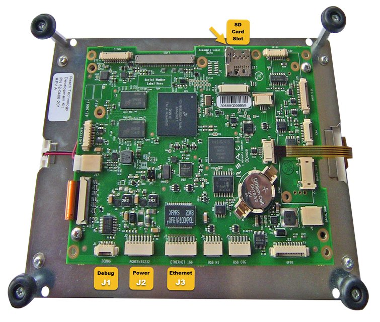
Connector and SD Card Locations
Insert the MicroSDHC Card
Insert the included microSD card into the SD card slot (J12).
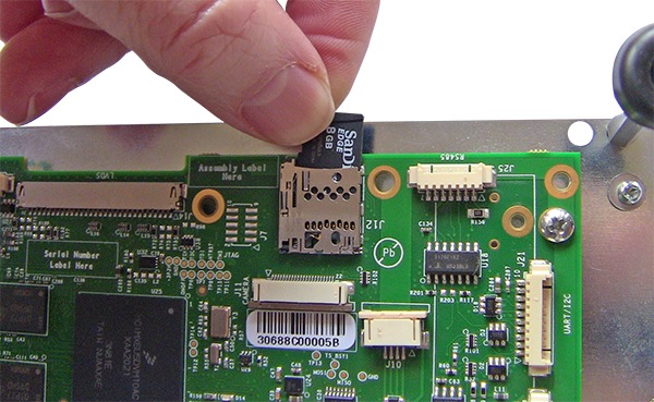
MicroSDHC Card Insertion
Connect the Cables to the G3 Module
With the controller board face-up, turn it so that the Debug port is facing you.
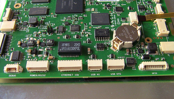
Board Positioning for Connecting Cables
Connect the Debug Interface Cable to the DEBUG port (J1).
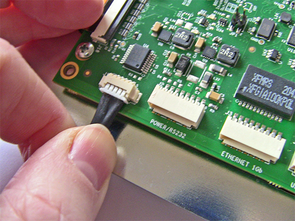
Connecting the Debug Interface Cable
Tip
The Debug Interface is not normally used in production. You will use it extensively during development. In a Qt environment, it can be a source of the end product application generated output shown in the Qt Creator -> Application Output tab.
In all environments, this is the Linux System Console so serious system and application errors will be logged to this port. If not using an IDE like Qt Creator, you should always have a terminal application open on this port.
Plug the AC mains cord into the AC adapter.
Connect the “Y” cable to the POWER/RS232 port (J2).
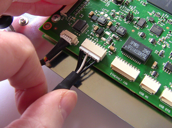
Connecting the “Y” Cable
Important
Do not power on the G3 module yet.
Locate the USB to RS-232 adapter and USB cable.
Insert the USB mini type-A connector on the cable into the mating socket on the adapter.
Attach the male DB-9 connector on the USB to RS-232 adapter to the female DB-9 on the “Y” cable.
Plug the USB type-A connector on the cable into your development host. Be sure to note the COM port on Windows or the /dev/ttyUSB<n> device special file if on Linux.
Connect the Ethernet Cable to the ETHERNET 1Gb port (J3).
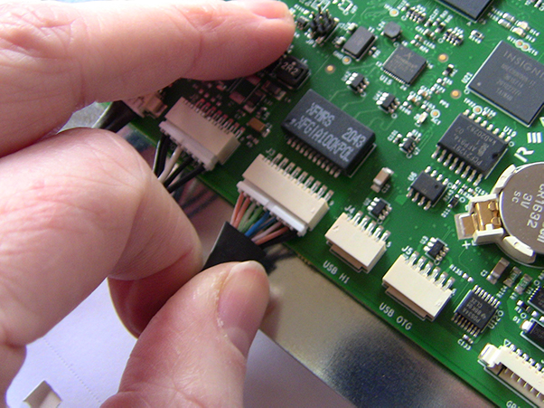
Connecting the Ethernet Cable
Use the Ethernet Inline Coupler and a standard Cat 5e patch cable to connect your G3 module Ethernet Cable to your network.
Important
Initial assembly is complete.
Do not power on the G3 module until you have completed the next section and have a working Terminal Emulator on your development host.